
Weather Station Froggy 1.0
 I was always keen on doing a little electronics project. The project was to built a weather station with its own microcontroller and data logging with little effort in mastering electronics but lots of opportunities to program.
My choice fell on the Arduino microcontrollers and an Arduino Ethernet controller using an Atmel microprocessor. The Arduino Ethernet board has the following possibilities:
- analog read (10 bit)
- analog write via pulse width modulation PWM
- digital write
- digital read
- bus connection to devices using the I2C protocol
- connection to the network with ethernet RJ45-jack
- access to SD cards as data logging device
Specifications
The weather station should be able to measure the following weather parameters:- temperature
- relative humidity
- air pressure
- brightness
- wind speed (later)
- wind direction (later)
- rain meter (later)
Principal working with Arduino Ethernet
USB Connection
The Arduino Ethernet does not come with an included USB connector as the Arduino Uno does. There are only 6 pins on the right hand side of the board, that have top be used to program the Arduino Ethernet, as the RJ45 jack is not active in the initial condition.In order to connect to the Arduino Ethernet an FTDI compatible USB cable is neccesary. I used a DeLOCK USB Cable with 5 V. The cable was soldered to a small plug, that fits the pins with the following layout:
| pin | meaning | colour |
|---|---|---|
| 1 | GND | black |
| 2 | CTS | brown |
| 3 | +5V | red |
| 4 | TXD | orange |
| 5 | RXD | yellow |
| 6 | RTS | green |
Measuring analog values
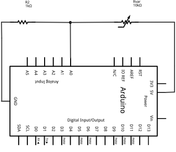
The Arduino family of controllers provide analog input on pins A0 to A6 with a 10-bit digital to analog conversion (DAC). In order to measure an analog voltage one needs to connect the voltage to one of the analog pins.
When executing the function i=analogRead(pin); it returns a value between 0 = 0.0 V and 210-1 = 1023 = 5.0 V.
In order to measure resisitivity, one needs to build up a voltage divider as given in the picture. The voltage divider measures the voltage, that drops at the resistor Rvar, with R2 being a constant resistor (e.g. 1 kΩ) and Us being the source voltage, normally 5.0 V or 3.3 V.
Rvar⋅Uvar=R2⋅U2
U2=(210-i)⋅Us
Uvar=i⋅Us
Rvar=R2⋅(210-i)/i
The resistivity is measured in ohms Ω.
To measure an electric current, just let the current flow through one resistor R with predefined resisitivity. By measuring the voltage that drops at the resistor one can calculate the electric current I:
I=U/R=(i/1024)⋅Us/R
Measuring with Froggy
Brightness
By measuring the brightness it is easy to tell, if the day is sunny or cloudy and when the sun rises or sets during the day. However, the sensor should be placed in such a way, that no direct sunshine can be measured. The measurement is quite easy. I use a photo resistor A905013 from PerkinElmer which has a reasonable resolution, also in the dark.
According to the above explanations I use a resistor R2=1 kΩ and Us=5.0 V. From the datasheet and from measurements the following equation was fitted:
E = 9588520 ⋅ Rvar-1.24238
Here a direct value of the brightness E in lux lx can be calculated from the resistivity in ohms Ω. The brightness E just has to be correlated with the cloud status and the time to estimate weather conditions and sunrise or sunset. This, of course, is highly dependent on the positioning of the light sensor and should be calibrated at first by calibration measurements and comparison with cloud status, etc. The reading and sensitivity of the photo resistor can be adjusted by changing the value of R2.
Air Pressure
A change in air pressure can indicate a change in the weather conditions, e.g. when a cold or warm front arrive. To measure the pressure I used the Motorola/Freescale MPX4115A sensor. It is an absolute pressure sensor with a range from 150 hPa to 1150 hPa. The air pressure normally lies in the range of 950 hPa to 1100 hPa, so the measurement range is sufficient. I use the 5 V power supply, that Arduino provides. The sensor has the following pin layout:| pin | meaning |
|---|---|
| 1 | Vout |
| 2 | GND |
| 3 | +5V |
| 4 | not connected |
| 5 | not connected |
| 6 | not connected |
p=1000.0 ⋅ Vout/1024 ⋅ 5.0/45.0 + 105.556The result is given in Pascal Pa. The output voltage depends on the input voltage. In case the input voltage differs a little (e.g. battery), the output voltage may vary so much, that faulty values are given. Therefore I recommend to measure the input voltage and correct the readings of the pressure sensor.
Programming Schemes
Setup
Links
Additional data for the whole project is provided here:- manual